
Image Credit: notthebee/seabiosbootsplash
Introduction
I’ve enjoyed using ThinkPads for several years. In particular older models such as the X220/X230, T420, and so on, because of their legendary customizability and durability. Long gone are the days of upgrading laptop RAM, since most modern systems have soldered memory. Battery replacements are tedious. Proprietary BIOS firmware resides on many chips, raising the ire of open source proponents, especially when subsystems like Intel Management Engine (ME) are a complete black box to users.
In this post, I’ll be partially disabling Intel ME using the me_cleaner tool, and installing coreboot, an open source firmware.
Prerequisites
As the title suggests, I’m using a ThinkPad X220. The process for installing coreboot on an X230, while similar, contains one important difference: the X230 has two flash chips, one for BIOS, and another for Intel ME, ethernet firmware, and so on. Conversely, the X220 has a single flash chip which contains everything: BIOS, ethernet firmware, Intel ME, etc. The X230 is a popular machine for many reasons, but for installing coreboot, the process is distinct.
Here are some other requirements:
- A separate computer
- CH341a1 USB Programmer. This can be found on eBay and Amazon for relatively cheap.
- Pomona SOIC82 clip, which can usually be purchased as a bundle with the USB programmer, though it may be a generic clip.
- A small phillips screwdriver (or micro-bit set) for X220 disassembly
- prying & opening tools for disassembly.
- optional: magnetic tray for screw organization.
I also recommend reading through some of the coreboot documentation to get a feel for the project.
Setup
I’m using another laptop with Ubuntu 20.04 installed. You can use another OS such as Debian, Fedora, or QubesOS, though I’ve only built coreboot with Ubuntu.
First, make a new directory for the project in your home directory, called x220-coreboot. Then navigate to its root:
mkdir x220-coreboot && cd x220-coreboot
In the next section, we’ll install flashrom, me_cleaner, and an Ada compiler3 called ‘gnat’. Lastly, download coreboot.
Flashrom & me_cleaner
Flashrom is used to identify, read, write, verify, and erase flash chips. We will use flashrom with our CH341A programmer to interact with our X220 chip.
To install on Ubuntu, you can use APT package manager:
sudo apt update && sudo apt -y upgrade
sudo apt install -y flashrom
After some quick googling, I found that my X220 SPI type is ‘MX25L6406E/MX25L6408E’. Keep this handy, as we will need it to use flashrom.
Next, we’ll download me_cleaner. me_cleaner (Intel Managenement Engine cleaner) is a utility for partially disabling the Intel Management Engine (mentioned earlier) that runs on directly on the flash chip. Unfortunately, we can’t fully disable ME, because our machine will not work properly. Using me_cleaner will render it almost useless, though. Here is the me_cleaner GitHub repository.
From the x220-coreboot directory, go ahead and clone me_cleaner.
git clone https://github.com/corna/me_cleaner.git
Install Ada Compiler: gnat-10
Since parts of coreboot are written in Ada, we need an Ada compiler. I used gnat-10, which Debian/Ubuntu users can install via APT:
sudo apt install gnat-10 -y
Check the Ubuntu packages site for more details on the gnat Ada compiler.
Download Coreboot
Downloading coreboot take a little while, so that’s why I decided to put in near the beginning of this tutorial. Simply run the command:
git clone --recursive https://review.coreboot.org/coreboot.git
Wait for coreboot to finishing downloading before moving to the next step.
Note: There is a mirror of coreboot hosted on GitHub. I found that recursively cloning from this mirror was faster than cloning from the primary coreboot repo. In the end, however, I used the primary repo to build coreboot, not the GitHub mirror.
Make ifdtool
Remember in the introduction when talking about the difference between the X220 and X230 flash chips? The X220 has a single flash chips that contains BIOS, Intel ME, and so on. So we need a way to split up our chip image into regions. For that, we will build a tool packaged with coreboot called ifdtool. Navigate to the coreboot/util/ifdtool directory and run make:
cd ~/x220-coreboot/coreboot/util/ifdtool
make
After that command finishes, we can go back to the root directory x220-coreboot.
Disassemble X220
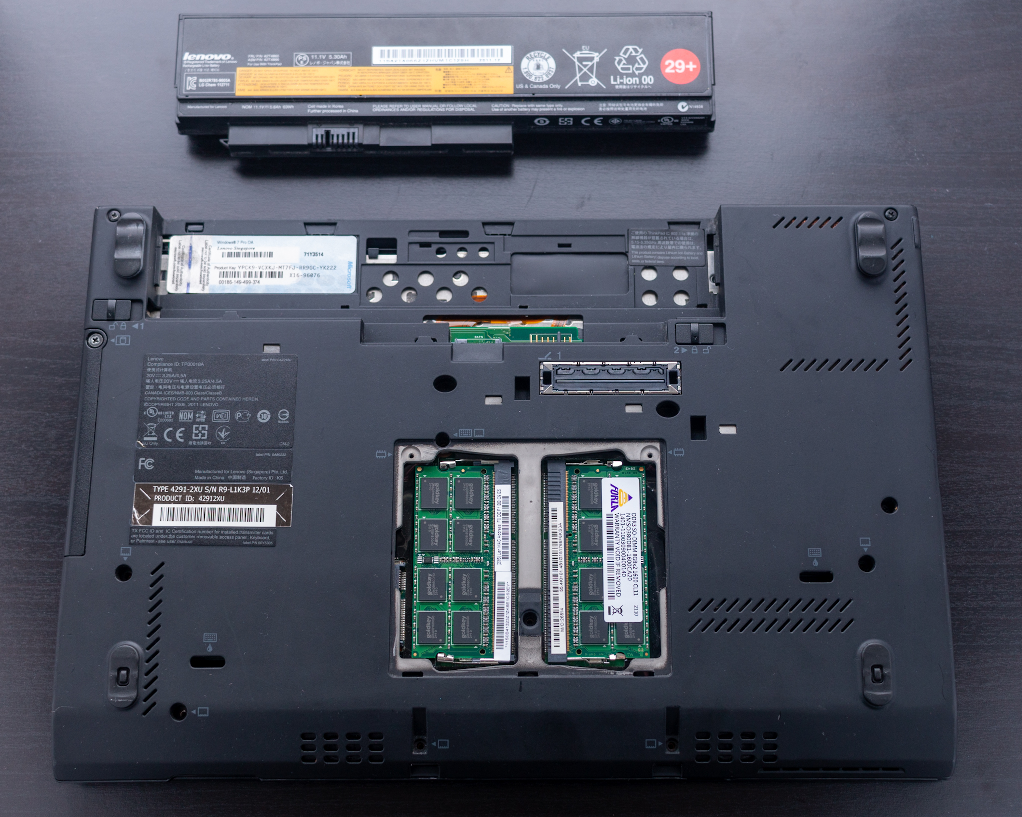
Remove the Battery!
Now it’s take to do some minor surgery on our X220. First, and this is very important, we need to remove the battery, and hold down the power button to drain whatever energy is left in the power supply capacitor(s) so we don’t cause any accidental electrical damage to our mainboard. Again:
- Remove any power adapter, then take out the battery
- Press and hold the power button for about 20 seconds.
Next, we need to remove the keyboard and the palm rest: remove the RAM cover on the bottom of the laptop by loosening the too screws at the top of the cover. Then remove all the screws labeled with the ‘keyboard’ and ‘chip’ icons. At this point, your work area should look similar to the picture above.
Turn over the laptop to its normal position and open. Then carefully press down on the keyboard, sliding the it toward the screen. You should feel it move several millimeters or so. Now pry up on the palm-rest end of the keyboard, and lift the whole keyboard up and out. Carefully rest it on the palm rest. Move slowly and deliberately, as the keyboard cable is still attached to the mainboard.

We can see the ribbon cable above. You can use a plastic tool, or your fingers, to gently pull up on the tab near the connection point. It will safely disconnect without much effort. Next, we need to remove the palm rest.
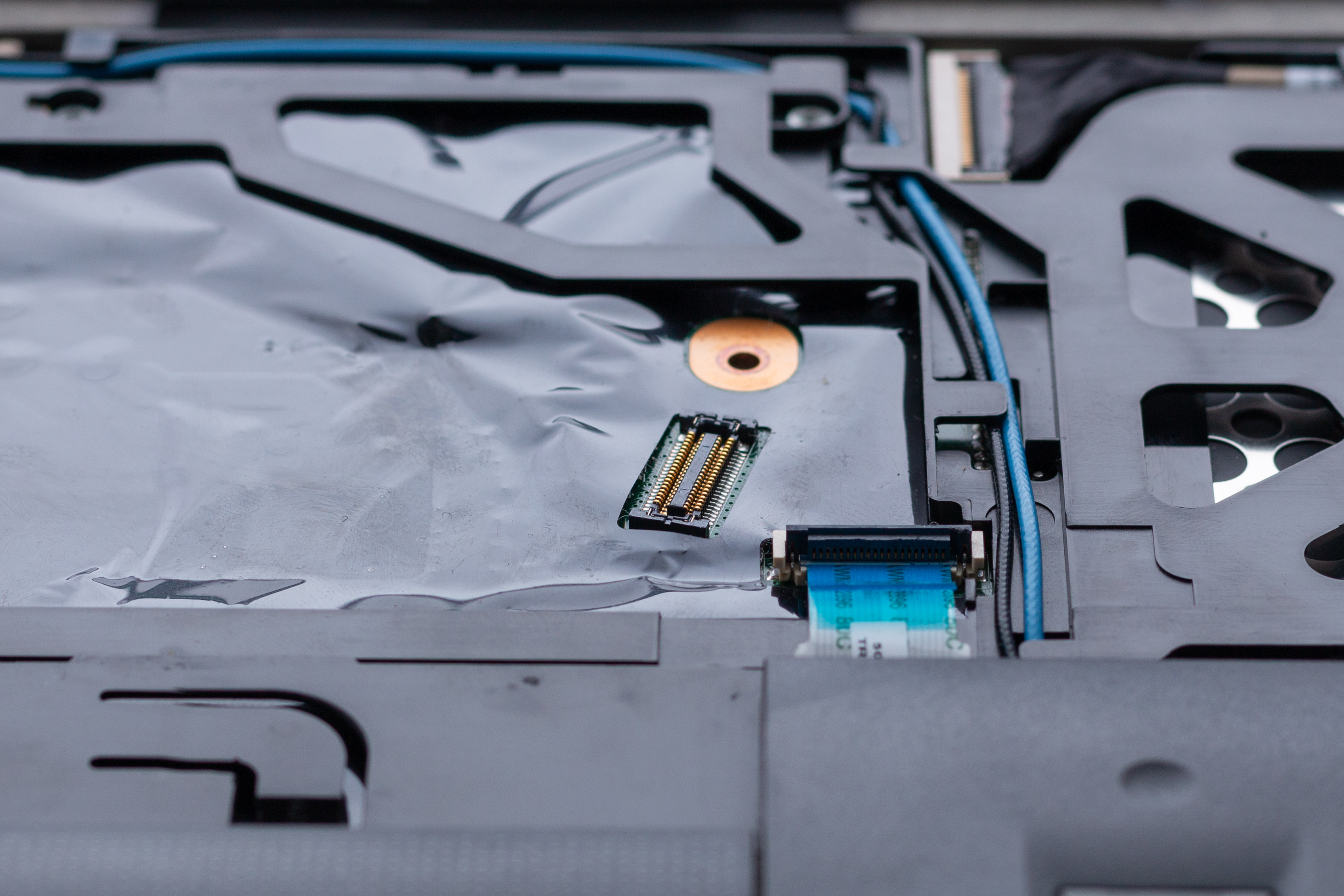
First, lift open the black tab holding the palm rest cable, where it’s attached to the mainboard. You can then use your fingers and remove the cable by pulling on the blue tab (see above picture) on the cable. Now, gently pry the right and left sides of the palm rest using one of your plastic prying tools until it comes loose. This should not take much force at all, so again, be gentle. Remove the palm rest and set it aside for now.
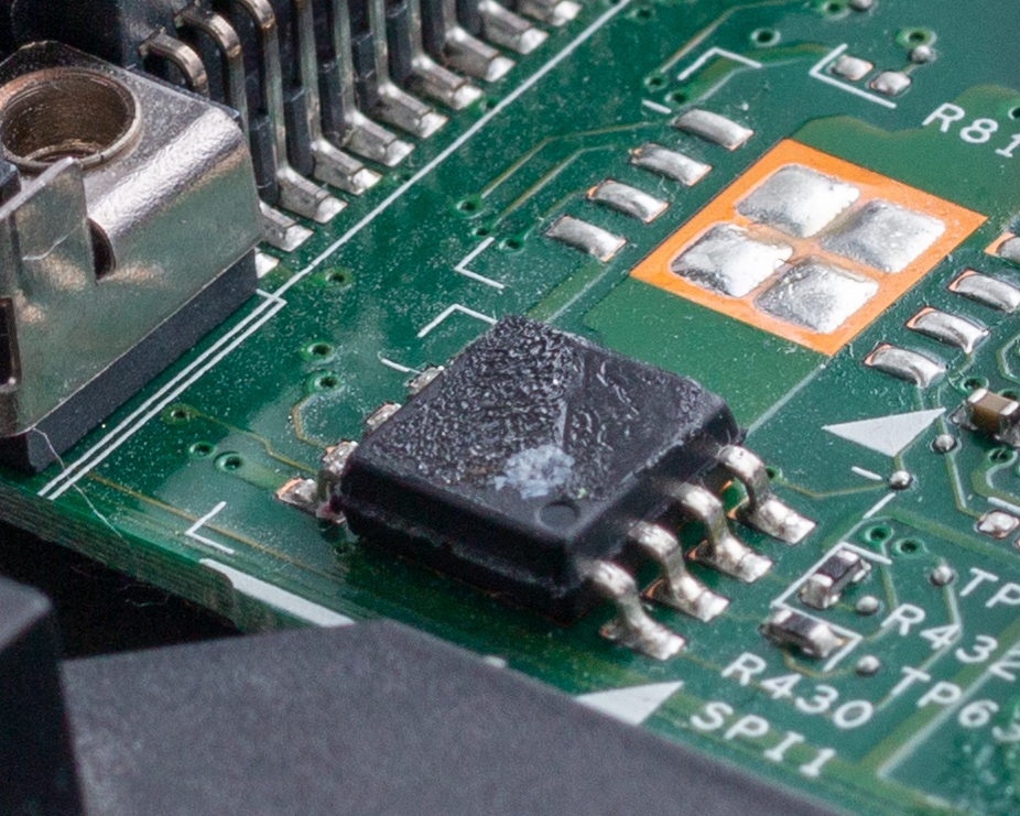
Expose the Flash Chip
On the bottom left corner where the palm rest was, and to the bottom right of the metal expansion bay cage, is the flash chip . We need to lift the black plastic film at the corner where it meets the expansion bay (see below picture). Gently fold over and secure the plastic so we can access the chip.
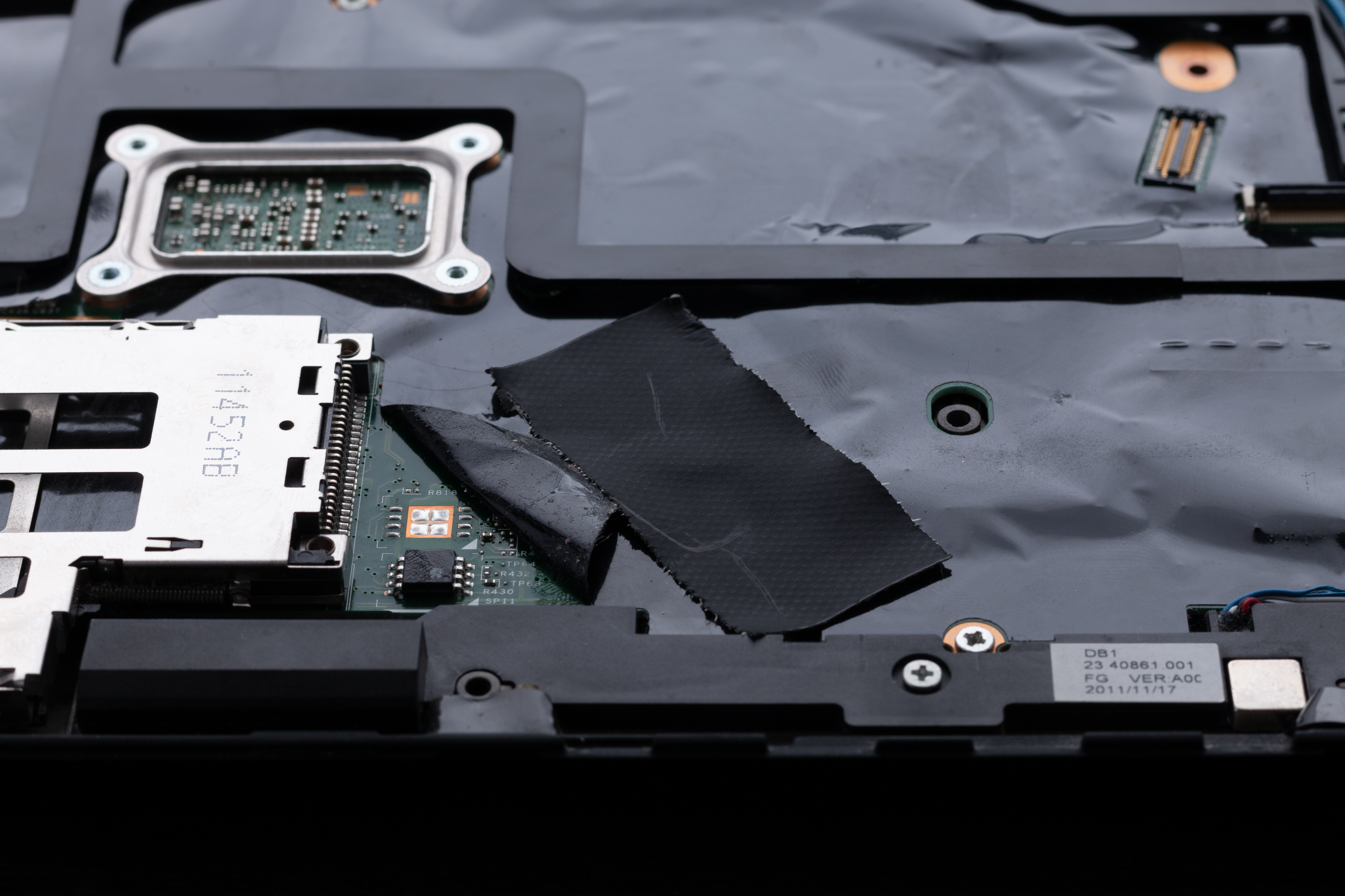
Above you can see the flash chip, (along with embarrassing amounts of dust) and the folded over plastic fastened with a small piece of tape.
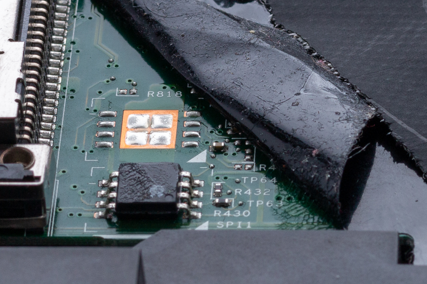
Here are some close-up pictures:
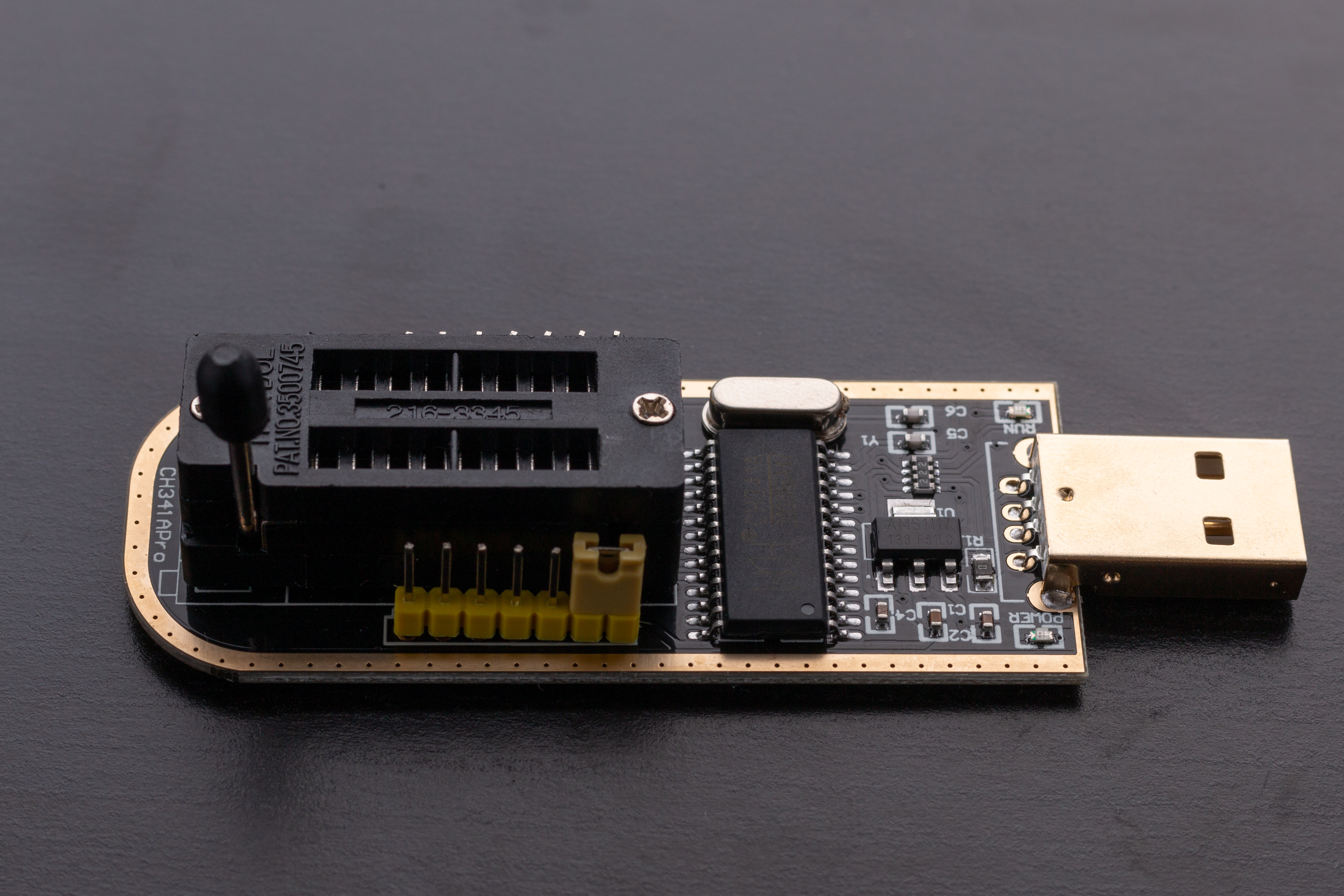
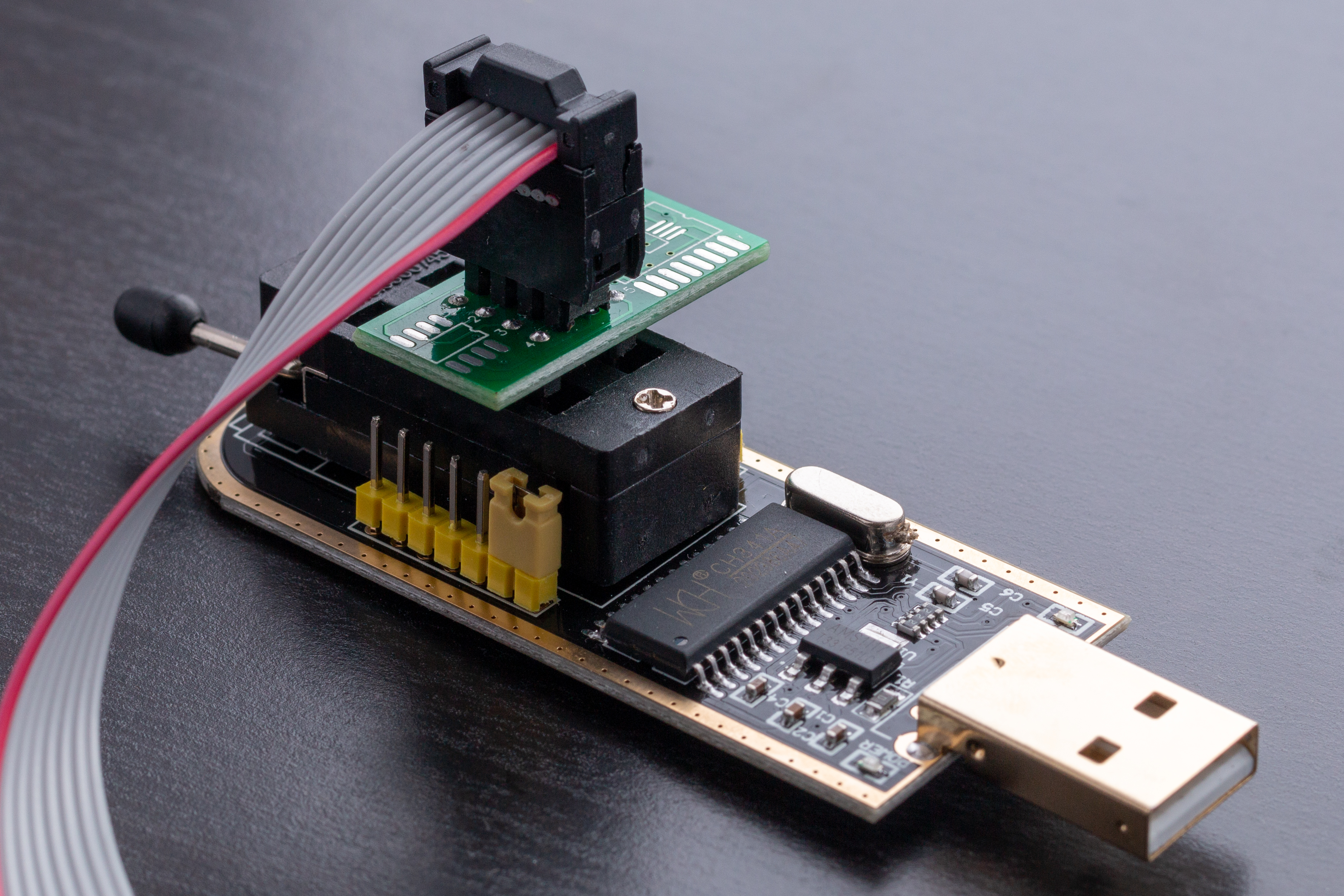
CH341a SPI USB Programmer & SOIC8 Clip
Here is a picture of the cable ribbon and PCB that came with the USB programmer. The PCB4 plugs into the programmer itself, and the other end of the ribbon is the SOIC8 clip that attaches directly to our flash chip.
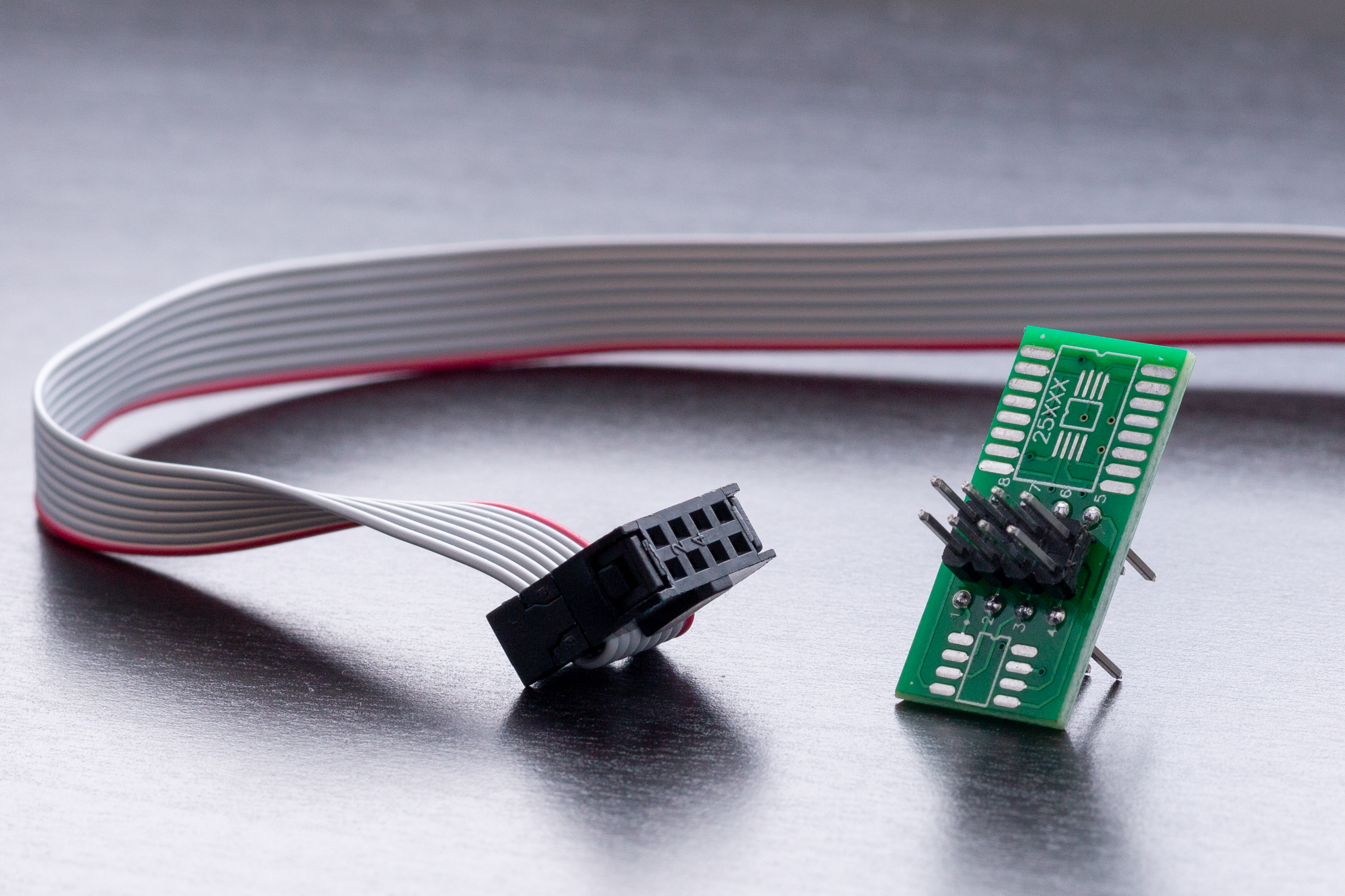
Now, insert the cable ribbon into the corresponding side of the PCB, like so:
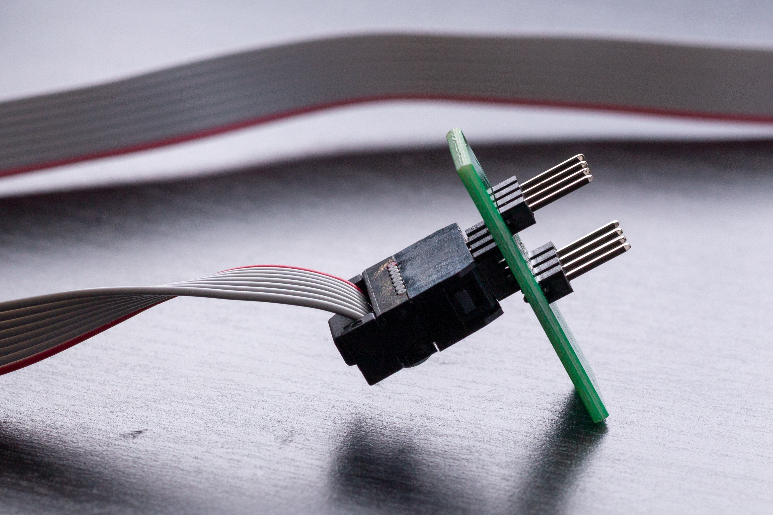
Next, with the USB programmer lever in the vertical position, connect the other side of the PCB. Be sure to insert the PCB into the eight slots nearest the USB side of the programmer. Once the PCB is attached, flip the programmer lever down to lock-in the PCB.
USB Programmer. Insert PCB into the eight (8) slots nearest the USB end:
Here is the connected PCB with the lever flipped into the (horizontal) locked position:
Time to Dump the BIOS
Thanks to this helpful post for the concise instructions.
We can finally start using our SPI programmer. You’ll want to get comfortable, make sure you have adequate lighting, and maybe a mounted magnifying glass. Or perhaps both. Note that the Pomona clip can be a pain to attach to the flash chip, as it is very delicate. Be patient.
Plug the programmer into your second computer where you installed flashrom earlier. You should see the red power LED indicator light up on the programmer, as shown below:
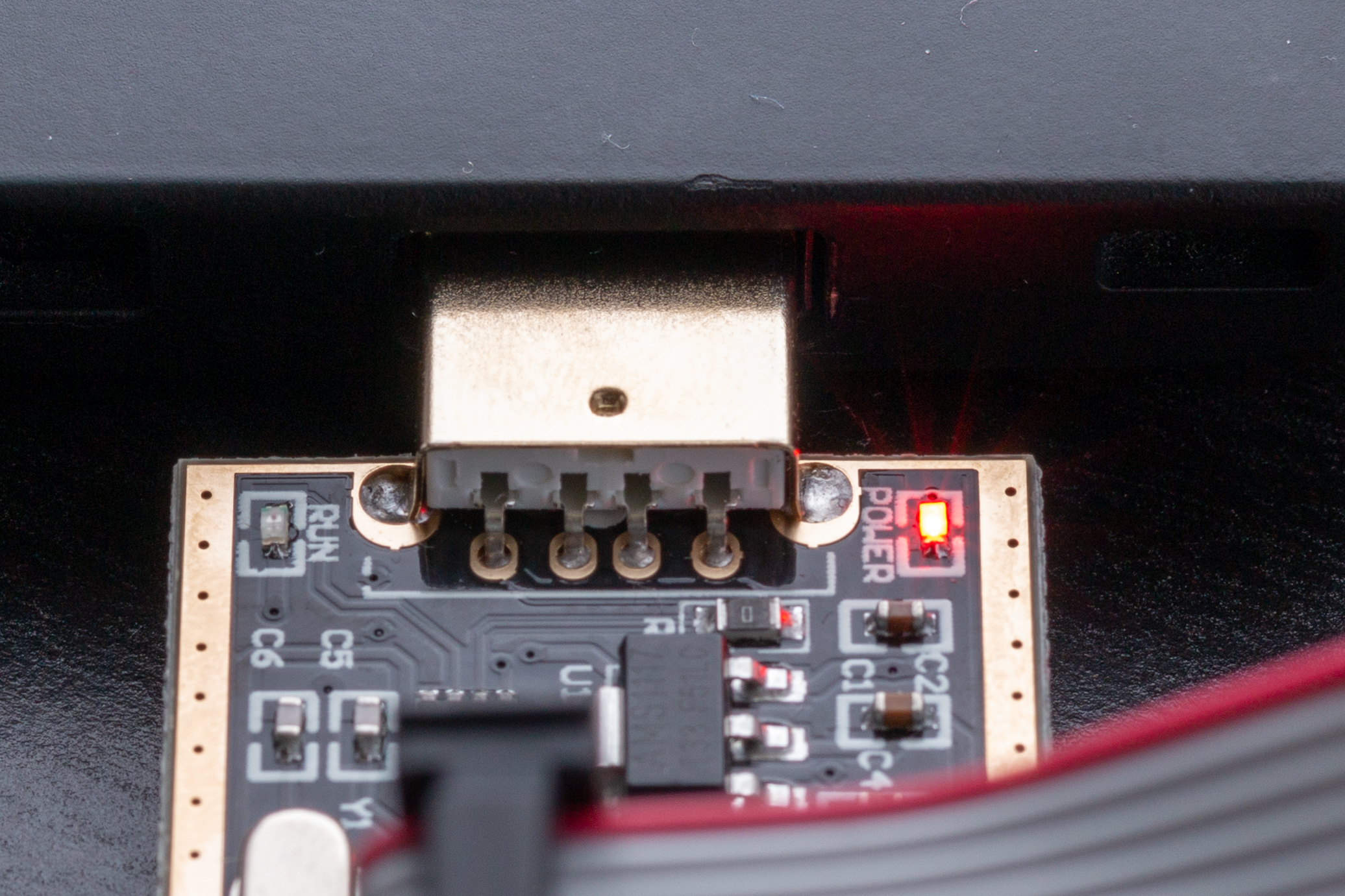
Now that we know it powers on, unplug the USB programmer from your second machine.
Take the Pomona clip and carefully attach it to the SPI flash chip. Again, this may take several tries to get right, so be patient. You want the metal contacts on the clip to align with the pins of the flash chip. Once connected, it should look something like this:
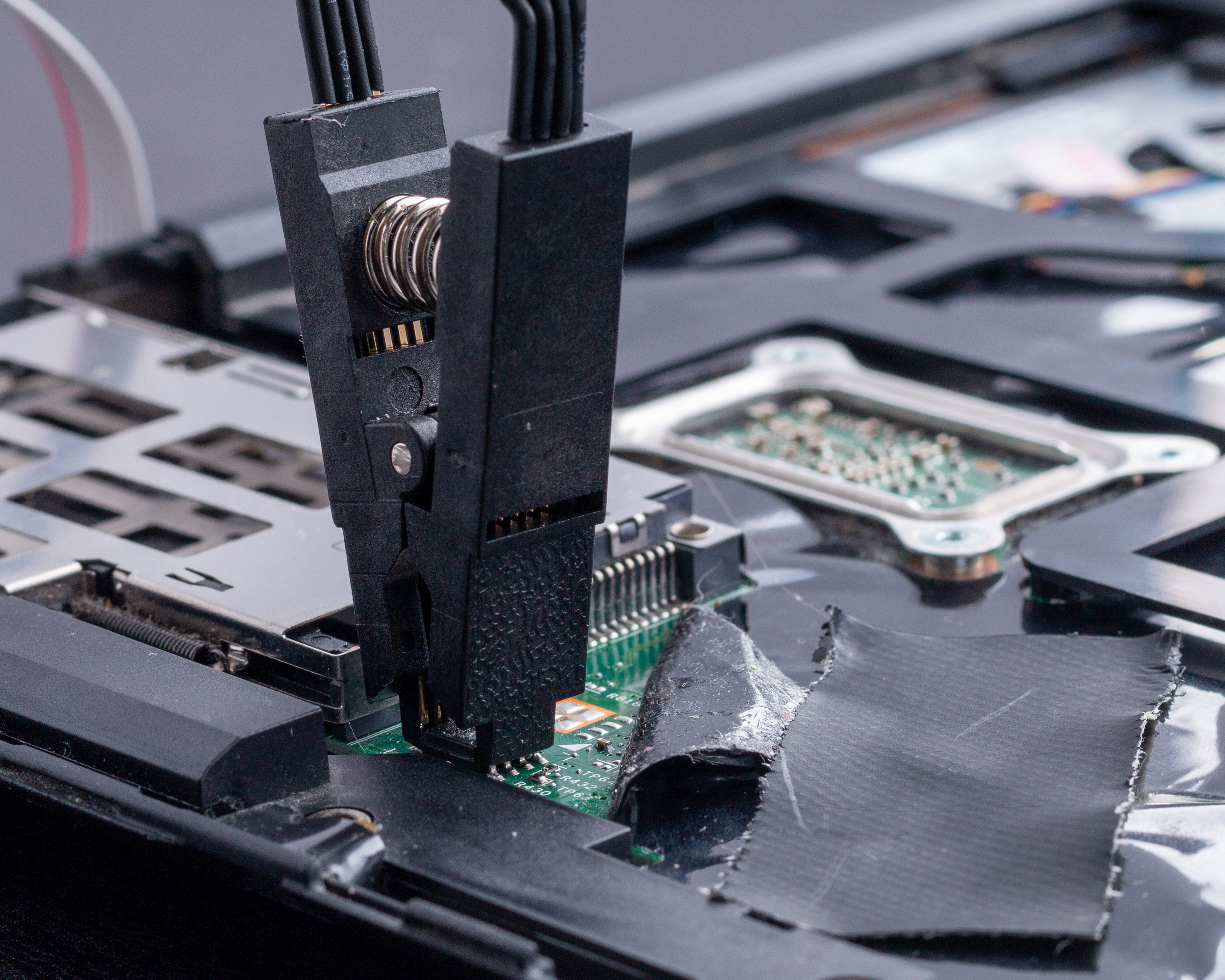
Once the clip is connected, reinsert the programmer into your second computer. The LED power light should again turn on. Now it’s time to dump5 the BIOS.
Make sure you are in the x220-coreboot directory, and then run the following command:
sudo flashrom \
 -c 'MX25L6406E/MX25L6408E' \
 -p ch341a_spi \
 -r x220-orig.bin
Breaking down this command into more detail, we have:
- The
-coption tells flashrom to probe only for the specified flash chip, in our caseMX25L6406E/MX25L6408E. - The
-poption is used to specify the programmer device. Flashrom supports many such devices, including ours, thech341a_spi. - Lastly, the
-roption lets flashrom know we want to read the flash chip contents and save them to a file specified after the-roption, i.e.,x220-orig.bin.
It’s a good idea to backup this file in the event you want to try and reinstall the stock firmware.
As suggested in the linked blog post, you can check that the dump was successful. Run the exact same command, except write to a second file called x220-orig-2.bin. Then use the diff command on both .bin files:
diff x220-orig.bin x220-orig-2.bin
If this exits without a message, there is no difference between the binary files and all worked as intended. Otherwise, check out flashrom common problems.
Now, unplug the USB programmer. I left the clip attached to the chip.
Run me_cleaner
Use cd ~/x220-coreboot/me_cleaner to navigate back into the me_cleaner directory. Run the following to see the usage options for me_cleaner:
python me_cleaner.py --help
Below is the full output. We are using the -S and -O options.
$ python me_cleaner.py --help
usage: me_cleaner.py [-h] [-v] [-O output_file] [-S | -s] [-r] [-t] [-k]
                     [-w whitelist | -b blacklist] [-d] [-D output_descriptor]
                     [-M output_me_image] [-c]
                     file

Tool to remove as much code as possible from Intel ME/TXE firmware images

positional arguments:
  file                  ME/TXE image or full dump

optional arguments:
  -h, --help            show this help message and exit
  -v, --version         show program\'s version number and exit
  -O output_file, --output output_file
                        save the modified image in a separate file, instead of
                        modifying the original file
  -S, --soft-disable    in addition to the usual operations on the ME/TXE
                        firmware, set the MeAltDisable bit or the HAP bit to
                        ask Intel ME/TXE to disable itself after the hardware
                        initialization (requires a full dump)
  -s, --soft-disable-only
                        instead of the usual operations on the ME/TXE
                        firmware, just set the MeAltDisable bit or the HAP bit
                        to ask Intel ME/TXE to disable itself after the
                        hardware initialization (requires a full dump)
  -r, --relocate        relocate the FTPR partition to the top of the ME
                        region to save even more space
  -t, --truncate        truncate the empty part of the firmware (requires a
                        separated ME/TXE image or --extract-me)
  -k, --keep-modules    don't remove the FTPR modules, even when possible
  -w whitelist, --whitelist whitelist
                        Comma separated list of additional partitions to keep
                        in the final image. This can be used to specify the
                        MFS partition for example, which stores PCIe and clock
                        settings.
  -b blacklist, --blacklist blacklist
                        Comma separated list of partitions to remove from the
                        image. This option overrides the default removal list.
  -d, --descriptor      remove the ME/TXE Read/Write permissions to the other
                        regions on the flash from the Intel Flash Descriptor
                        (requires a full dump)
  -D output_descriptor, --extract-descriptor output_descriptor
                        extract the flash descriptor from a full dump; when
                        used with --truncate save a descriptor with adjusted
                        regions start and end
  -M output_me_image, --extract-me output_me_image
                        extract the ME firmware from a full dump; when used
                        with --truncate save a truncated ME/TXE image
  -c, --check           verify the integrity of the fundamental parts of the
                        firmware and exit
Next, the following command partially disables Intel ME:
python me_cleaner.py -SO ../x220-no-me.bin ../x220-orig.bin
- The
-Soption means soft-disable. -Ooption saves the modified firmware image to a new file, rather than modifying the original.- The file
x220-no-me.binis our new binary image, partially cleansed of Intel ME, while../x220-orig-binis our original.
Soft-disable means we are not fully removing Intel ME: without a valid firmware, the PC will shut down after 30 minutes. The work-around we are implementing modifies Intel ME so it’s only active during the boot process.6
Build Coreboot
We are getting close to building coreboot, but first we need to run ifdtool.
Navigate to the coreboot/util/ifdtool directory. We built the ifdtool earlier, and now we can use it to move the correct pieces of the flash image into the corresponding coreboot blobs directories. The full list of commands is below.
Run ifdtool
# runs ifdtool and separates regions of the flash chip image for us

./ifdtool -x ~/x220-coreboot/x220-no-me.bin

cd ../..

mkdir -p 3rdparty/blobs/mainboard/lenovo/x200

cd 3rd party/blobs/mainboard/lenovo/x220

mv ~/x220-coreboot/util/ifdtool/flashregion_0_flashdescriptor.bin \
 descriptor.bin

mv ~/x220-coreboot/util/ifdtool/flashregion_2_intel_me.bin \
 me.bin

mv ~/x220/coreboot/util/ifdtool/flashregion_3_gbe.bin \
 gbe.bin
The -x option extracts the Intel FD modules6 from the x220-no-me.bin file we created. The full list of usage options for ifdtool can be found below.
usage: ./ifdtool [-vhdix?] <filename>

-d | --dump: dump intel firmware descriptor
-f | --layout <filename> dump regions into a flashrom layout file
-t | --validate Validate that the firmware descriptor layout matches the fmap layout
-x | --extract: extract intel fd modules
-i | --inject <region>:<module> inject file <module> into region <region>
-n | --newlayout <filename> update regions using a flashrom layout file
-O | --output <filename> output filename
-s | --spifreq <17|20|30|33|48|50> set the SPI frequency
-D | --density <512|1|2|4|8|16|32|64> set chip density (512 in KByte, others in MByte)
-C | --chip <0|1|2> select spi chip on which to operate
can only be used once per run:
0 - both chips (default), 1 - first chip, 2 - second chip
-e | --em100 set SPI frequency to 20MHz and disable
Dual Output Fast Read Support
-l | --lock Lock firmware descriptor and ME region
-r | --read Enable CPU/BIOS read access for ME region
-u | --unlock Unlock firmware descriptor and ME region
-M | --altmedisable <0|1> Set the MeDisable and AltMeDisable (or HAP for skylake or newer platform)
bits to disable ME
-p | --platform Add platform-specific quirks
adl - Alder Lake
aplk - Apollo Lake
cnl - Cannon Lake
ehl - Elkhart Lake
glk - Gemini Lake
icl - Ice Lake
jsl - Jasper Lake
sklkbl - Sky Lake/Kaby Lake
tgl - Tiger Lake
-S | --setpchstrap Write a PCH strap
-V | --newvalue The new value to write into PCH strap specified by -S
-v | --version: print the version
-h | --help: print this help

<region> is one of Descriptor, BIOS, ME, GbE, Platform, res1, res2, res3
Configure Coreboot
Next we configure coreboot, which is straightforward:
cd ~/x220-coreboot/coreboot
make menuconfig
This will bring up an interactive shell with configurable settings:
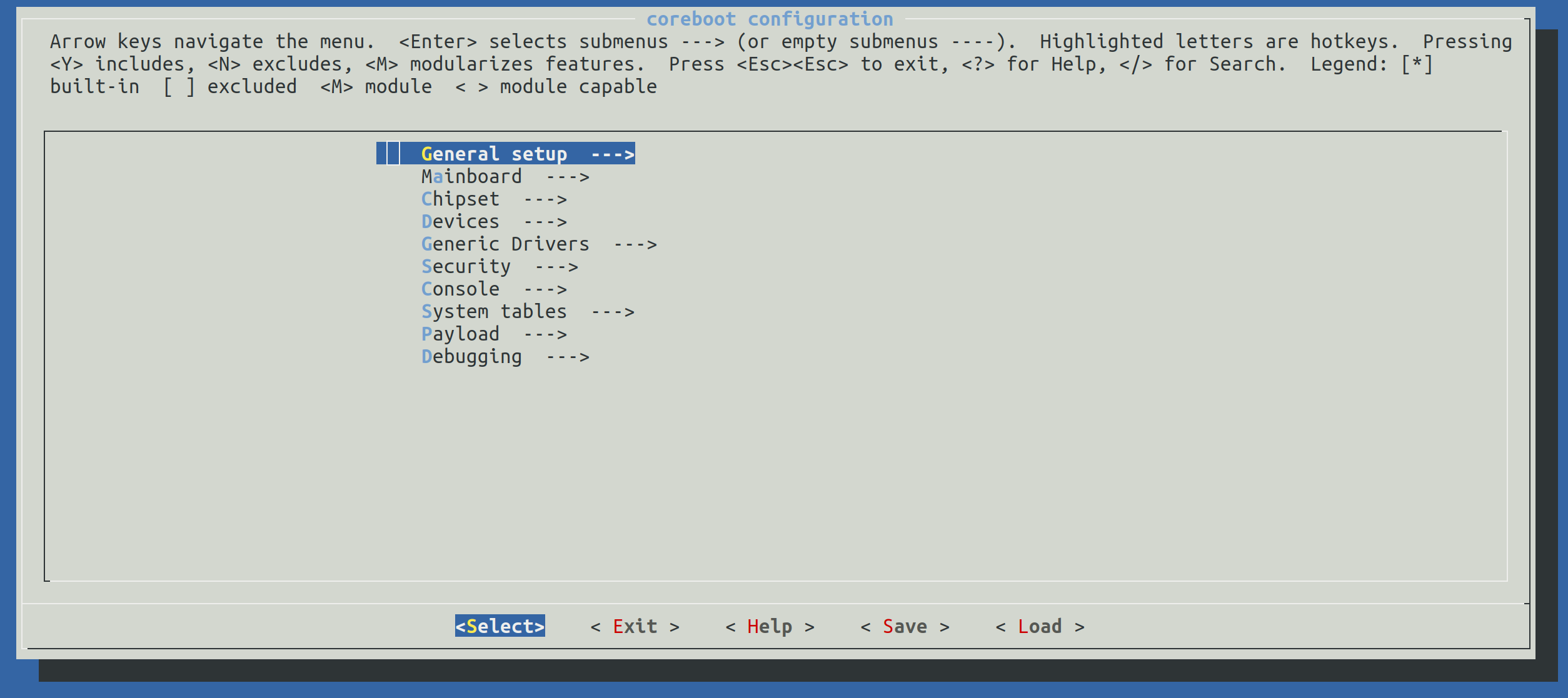
The following settings were changed (again thanks to this post for the suggestions). Note: read the prompt when opening menuconfig, and use y/n to select/deselect settings where appropriate.
Mainboard: In the Mainboard settings, change mainboard vendor to Lenovo, and mainboard model to Thinkpad X220.
Chipset: In Chipset settings, select (using y) the following along with their corresponding locations/paths we created earlier using the ifdtool:
- Add Intel descriptor.bin file
- Add Intel ME/TXE firmware
- Add gigabit ethernet configuration
Generic Drivers: Select PS/2 keyboard init
Secondary Payloads: Select Load coreinfo as a secondary payload and Load nvramcui as a secondary payload.
Save the configuration file to the default location, and exit menuconfig.
Optional: I may cover this in a separate tutorial, or append this one, but I’d also like to add a custom bootsplash image. You can do this by selecting
Add a bootsplash imagein theGeneral Setupsettings. A bootsplash image can also be added after coreboot is installed. See this guide on GitHub.
Build Cross Compiler and Coreboot
Now we need to build a compiler targeting i386 and the iASL ACPI7 compiler. We then use both of these compilers to build coreboot. This will take a bit of time, depending on your host machine.
make crossgcc-i386 CPUS=$(nproc)
make iasl
make
Recall that nproc prints the number of processing units available to the current process.
After the build process completes, you should see a Built lenovo/x220 message. Check that the new firmware image, coreboot.rom, is in the build directory.
Flash New Firmware Image
We’re almost done. Our last step is to run flashrom, writing the new image to our chip:
sudo flashrom \
  -c 'MX25L6406E/MX25L6408E' \
  -p ch341a_spi \
  -w build/coreboot.rom
Here, the -w <file> option tells flashrom to write <file> to flash.
Flashrom verifies the data was written correctly by automatically reading back the data after it is written.
Test
Now it’s time to plugin the keyboard, reattach the battery and/or power supply, and boot up the machine. The SeaBIOS boot menu should appear (in its very minimal form). You can then press Esc, followed by a number key corresponding to the boot option of your choosing, e.g., an SSD with Linux on it, a USB drive, and so on. If this works, congrats! You can now reapply the plastic over the flash chip, and reassemble the palm rest and keyboard.
Conclusion
This was a genuinely fun project I’ve been wanting to do for a while. Though building and flashing firmware to your own laptop my seem like an obscure and unnecessary task, the skills and tools required are minimal. I should note that it is possible to dump/flash your firmware with something like a raspberry pi, not just an SPI programmer (though the programmer seemed like a good fit for a first-timer). There are many tutorials on YouTube and elsewhere covering the Raspberry Pi method. I also recommend visiting the coreboot subreddit for questions/help.
If you have any feedback, please feel free to contact me via Twitter or email.
Also known as a BIOS programmer, one of the primary use cases for this chip is for programming SPI flash chips. SPI stands for Serial Peripheral Interface. ↩︎
A compiler for Ada is required because coreboot uses libgfxinit, which is written in Ada. libgfxinit is a graphics initialization (i.e., modesetting) library for embedded environments. Read more about libgfxinit here. ↩︎
Printed Circuit Board (PCB) ↩︎
A dump is essentially unedited data taken directly from it’s storage medium. In our case, we are taking the state of the flash chip as-is, and saving it to our second computer as a backup. In programming, to dump anything means to get its content, e.g., a memory/core dump. ↩︎
For more detailed information, read the ‘How does it work?’ page on the me_cleaner GitHub. ↩︎ ↩︎
ACPI stands for ‘Advanced Configuration and Power Interface’, which is an open standard used by operating systems for tasks like power management, hardware discovery and configuration, and so on. It’s essentially a hardware interface. Additionally, iASL is an ASL compiler, where ASL stands for ‘ACPI Source Language’. Read here for some amusing criticism of ACPI by Linus Torvalds. ↩︎